The degree of light diffusion depends on the type of lighting device, so from the light source, reflectors, relative to the scattering veil, and on the distance of the illuminating tool from the object. (The distance condition applies, of course, only to the incandescent light source, etc. It does not apply to solar lighting). The degree of dispersion always changes in the case of reflection of the luminous flux from matte surfaces. The cloudiness of the sky changes the dispersion of lighting to a great extent. The diffusion of light can be consciously and deliberately adjusted, therefore, it is part of the photographic workshop.
We distinguish non-diffused lighting (point, directional, streaming, focused, spicy) and diffused lighting (soft, dispelled, mild).
Unscattered light comes from a small source (drawing 5, a), distant (drawing 5, b) lub of the collimator (drawing 5, c). Collimator - Lenticular optical system, used to receive a beam of parallel rays. Condenser - optical system, focusing the rays at the right point.
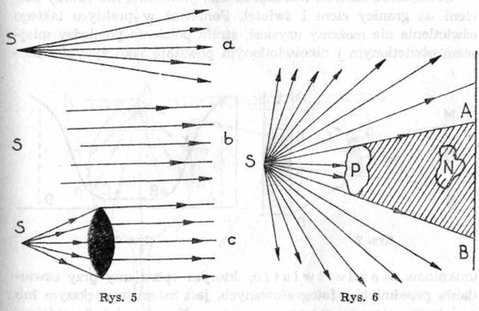
Unattainable in photographic practice, perfectly unscattered light runs from the source, whose area is close to the point. We call them spotlight, whether, whether it passes through the lenticular system or not. So that after passing through such a lens system, the light is unscattered, the light source must be "point". Light, which, for example, has passed through the optical system of the collimator and is a beam of parallel rays, we call stream light (drawing 5, c).
Opaque items, standing in the way of light, are the cause of shadows. A shadow is a space that is hidden from the source of light, outside of the illuminated object (drawing 6, P). Item (N) placed in shadow space is not illuminated. On the surface lying in the path of the shadow, the image of this shadow AB is formed (drawing 6). In colloquial speech, we call it a shadow.
Undiffused light casts sharp shadows from objects in its path, that is why it is often called sharp light.
The boundary between the lit and unlit part of the surface, on which the shadow falls, it can be more or less sharp, the transition can be abrupt or mild, it can be a clear boundary line or a strip of tones varying from light through semitones to dark. This transition zone between shadow and light is penumbra.
Lighting perfectly undispersed, point, it does not create partial shadows on the border of shadows and highlights. Because in practice we cannot obtain such lighting, the penumbra zone between the illuminated and unlit places arises as an inevitable phenomenon. every light, which we use when illuminating photographed objects, it is therefore more or less dispersed.
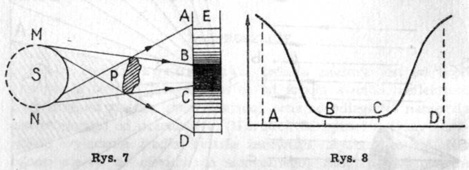 In the drawing 7 we see the light source S, np. milk bulb. It illuminates the object P with half of its surface (od M do N). The light from the other half is completely lost to the item except when using a reflector. The shadow of object P falls on a bright surface E, creating an AD blackout on it. This obscuration is greatest within BC, while zones AB and CD are brighter. These are the penumbra zones, i.e. places illuminated only by part of the surface of the light source. Drawing 8 shows, that when the shadow BC is darkened evenly over the entire surface, this blackout of the midtones is gradual (AB i CD).
The larger the penumbra zone, the more the lighting is diffused. Degree of illumination, the distance of this plane from the pre-ask depends on three fundamental factors: the cross-sectional area of the object casting the shadow, and the distance from the object to the surface, where the shadow is formed.
The nature of the luminous surface also plays a role here, especially when it is a translucent body, np. milk bulb bulb, frosted glass or muslin stretched over the frame. The scattering capacity and character of such translucent surfaces vary.
There are two types of transmitted light scattering : matte and opal dispersion. The formation of the matte dispersion is shown in the figure 9.
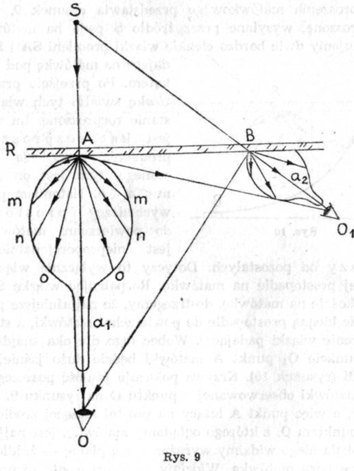 Undiffused light, sent by the source S falls on the screen R. We consider two very thin beams of rays SA and SB, falling on the screen from different angles. After passing through the focusing screen, the light of these beams will be scattered. The greater the scattering angle of the ray scattered by it, the weaker he is: m < n < o. On the other hand, the ray coming out perpendicular to the surface of the focusing screen (a1) is disproportionately brighter than the others. This applies to the SA beam only, falling perpendicularly on the screen. Considering the SB beam, falling obliquely on the mat, we notice, that the brightest rays a2 do not run perpendicularly to the surface of the focusing screen, a are an extension of the incident beam. Therefore, for the eye located at point O1, point A of the focusing screen will be much brighter than point B (drawing 10).
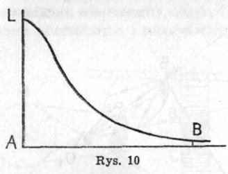 The curve shows the brightness of individual places of the focusing screen observed from point O in the figure 9. Center of the focusing screen, so the point A lies on the straight line connecting the light source S with the point O, from which we watch the matric, is the brightest. Around him we see a clear bright spot - a source of light, lying outside the mat. We see her out of focus, but the spread is so small, that we can, in some cases, distinguish the contours of the shapes of the light source. Looking obliquely, np. from point O1 (drawing 9), we will see less sharpness of these shapes, with the brightest spot on the focusing screen moving to point B.
Opal dispersion, such, which light undergoes after passing through opal glass, has a different character. For opal glass R (drawing 11) beams of SA and SB rays from the light source S are incident.
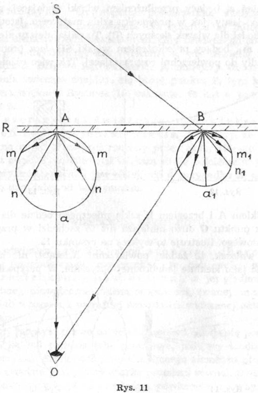 Of course, according to the principle of the square of the distance, point A will be brighter than point B. At point A the rays scatter similarly, like frosted glass, With this difference, that radius a, being an extension of the incident beam, is not so blatantly clear, like frosted glass. A significant difference occurs for oblique bundles (B). Radius m1 will not be the brightest here, being an extension of the SB bundle, but radius a1, perpendicular to the scattering surface. So the difference between me
between the center A and the edge B of opal glass will be much smaller for the observer from point O than it is in the case of frosted glass. This is illustrated by the graph in the figure 12.
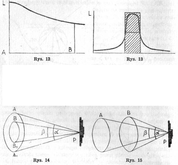 Hence the conclusion, that no luminous surface can be treated as optically perfectly homogeneous. In the case of the focusing screen, only a small circle of its center will have such an area (drawing 13). A hatched surface indicates a disc that is practically uniform in brightness.
The degree of diffusion of the reflected light depends on the angle of the light source. It is contained between the edges of the surface of the light source and the elementary point illuminated. We will call individual illuminated elementary points, very small, evenly illuminated surface elements, quite large though, for dispersion to occur. The larger the luminous surface, the greater the degree of dispersion. In the drawing 14 point P is the elementary illuminated point. When it is illuminated by the surface AA1, we obtain the beam angle a, when illuminated by a smaller area BB1 - beam angle P, smaller than a. The closer the luminous surface is to point P, the greater the beam angle. Drawing 15 indicates, that angle a is greater than angle β.
The wider the beam angle, the greater the degree of light diffusion, Meaning, that a shadow falling on point P or cast by a body, whose element is point P, will have a larger penumbra zone in the case of A, when the light source is closer, than in the case of B, when it is farther from that point.